Lighting on a minibike is usually pretty basic, and often absent. On the latest build, the 1980 Honda Chrome Custom, a simple battery-less pit bike design was initially used to get things going, but without a battery, things like horns and relays were not functioning well, if at all, and there was no capacity to add things like instruments and ground effects (for Parade of Lights Elvi rides.) Adding a battery was challenging because of space issues. The decision was made to change out the stator for a ground lifted, or floating stator and a full wave rectifier to change the system. Other considerations were that a key switch was now needed, and along with the handlebar buttons, used smaller gauge wire unsuitable to carry the electrical load. The relays were added to turn the lights on and switch to brights.
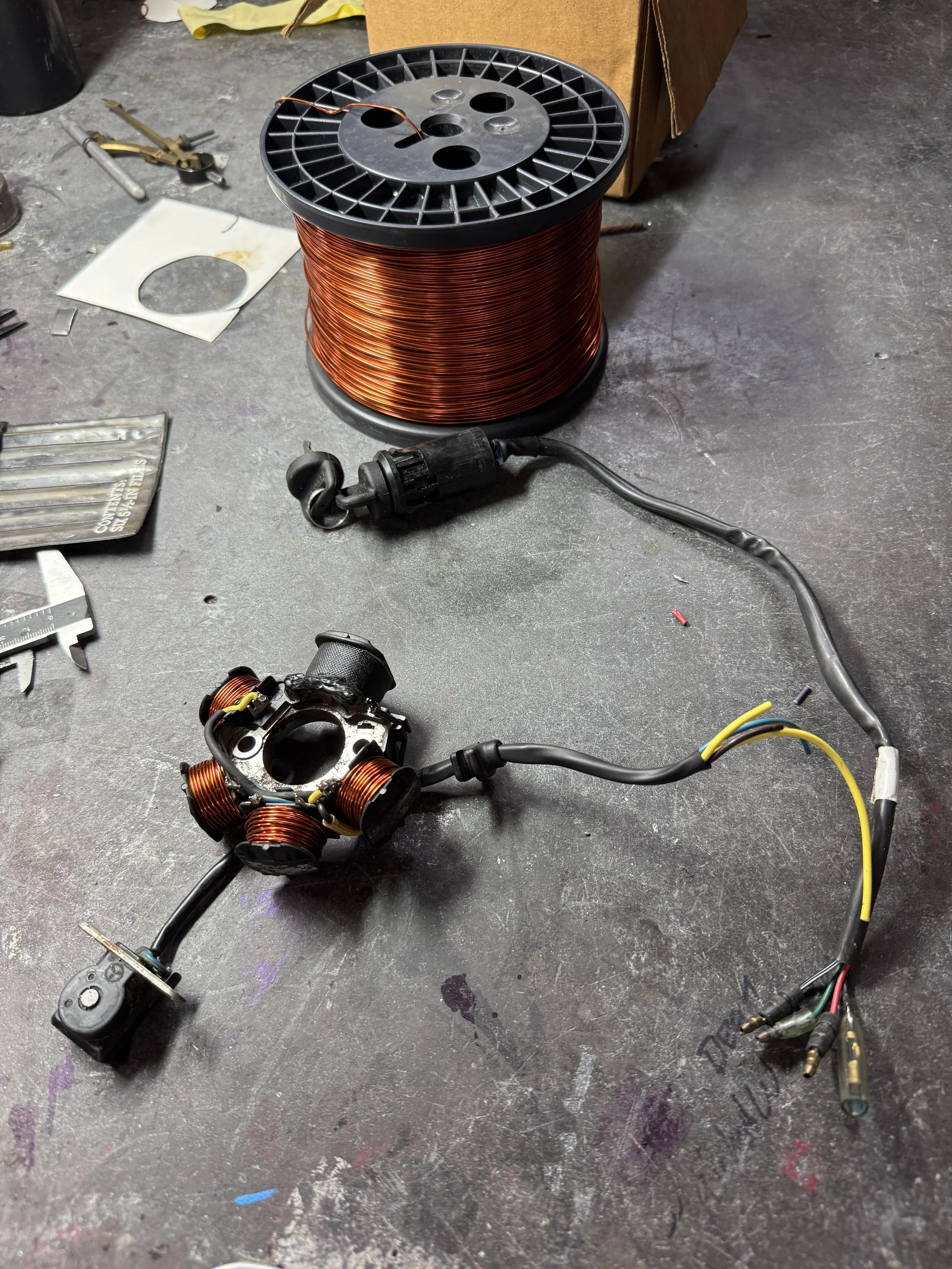
The original stator was wrapped with magnet wire and the output was changed to a two-wire “floating stator” type. It would have been faster changing the output of the Ricky stator to this configuration, but when experimenting with a new system, I like to leave the option to return back to original if the experiment is not successful. The 20 gauge OEM Honda key switch wires, laid next to the 18 gauge output wires of the stator are clearly smaller. The handlebar switches are rated for a headlight, but my experience with these unbranded aftermarket switches is that they produce heat, and sometimes fail because of it. With the small gauge key switch wiring and the handlebar switch issues, it was decided to use a relay system that passes current in a circuit parallel to the switched power key circuit.
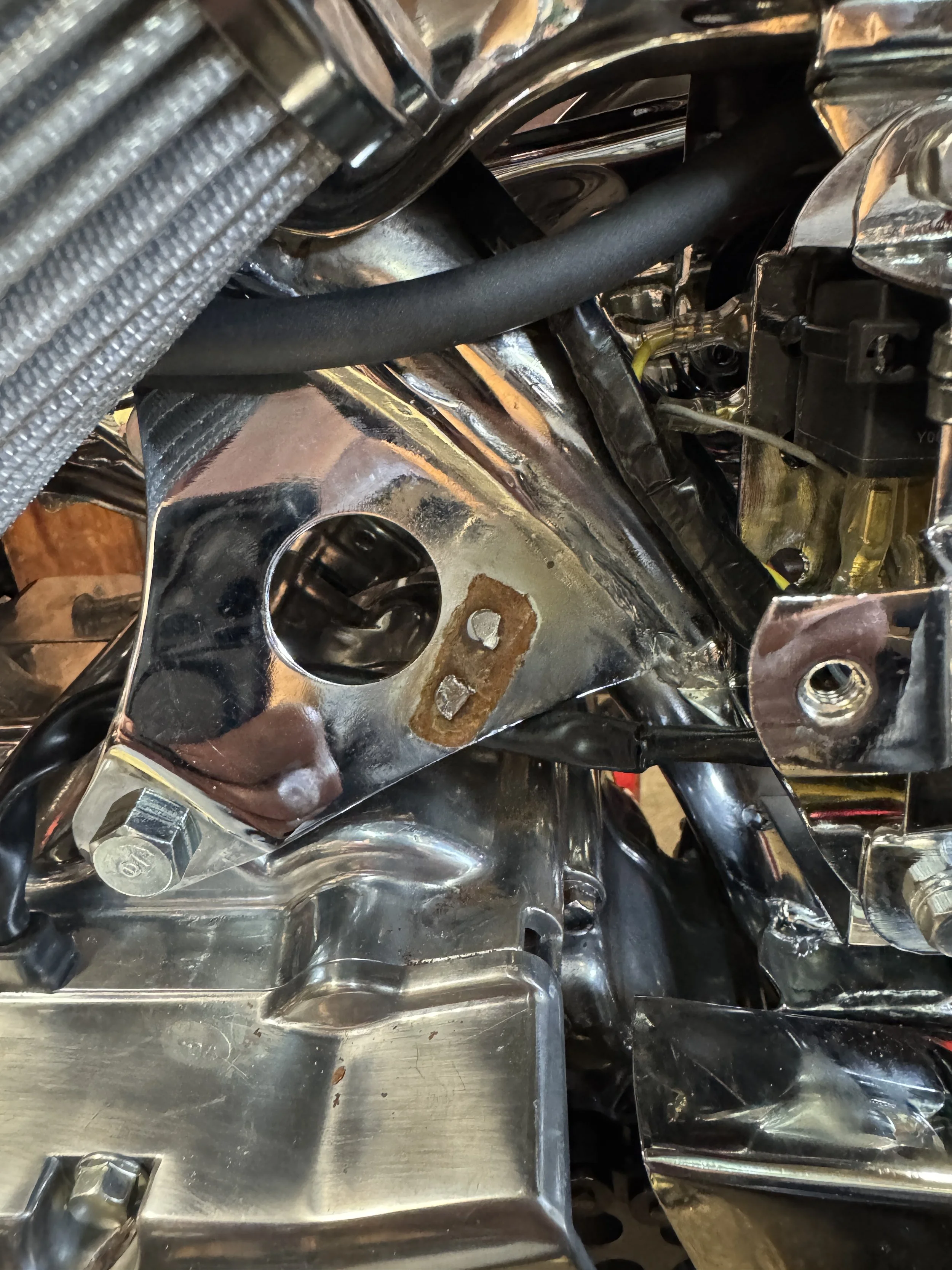
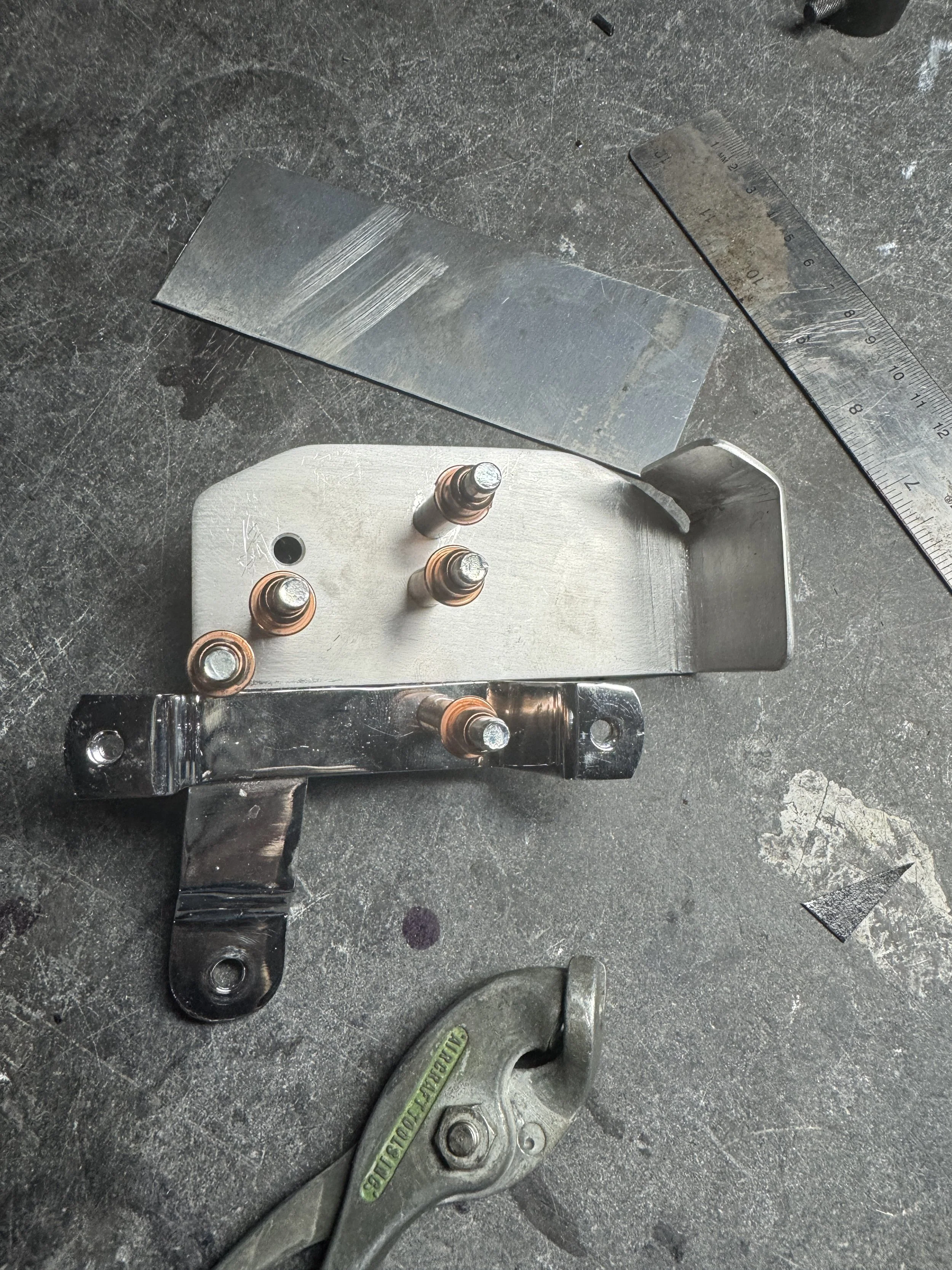
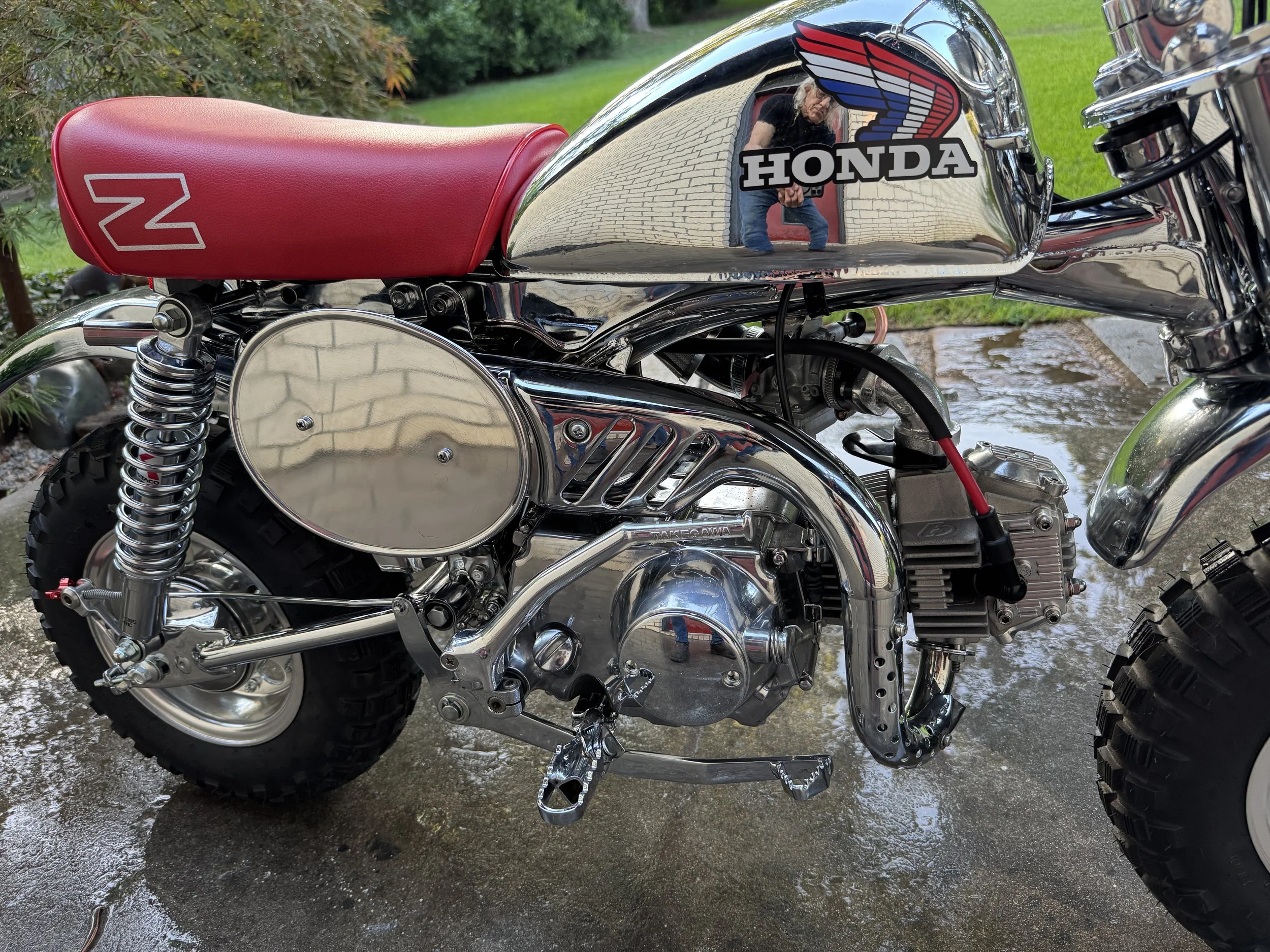
One of the reasons the particular key switch was used was because it fits into the hole in the left engine mount. Although it clicks into the hole, it pops out easily, and spins freely. In past builds, I have welded a plate to the inside of the engine mount that has the right thickness and cut-outs to lock it in tight. The frame hole would then be drilled out to allow the switch to sit recessed within the hole. This pushed the switch a little further back, but was otherwise a good mod. Since the frame had already been chrome plated, welding on the bracket would present some problems. A second problem was the factory clip for the ignition pigtail, adjacent to the hole. It had been badly damaged during the plating process, and was not being used. The rusty spot in the picture is where it once was, with a couple spot welds still visible.
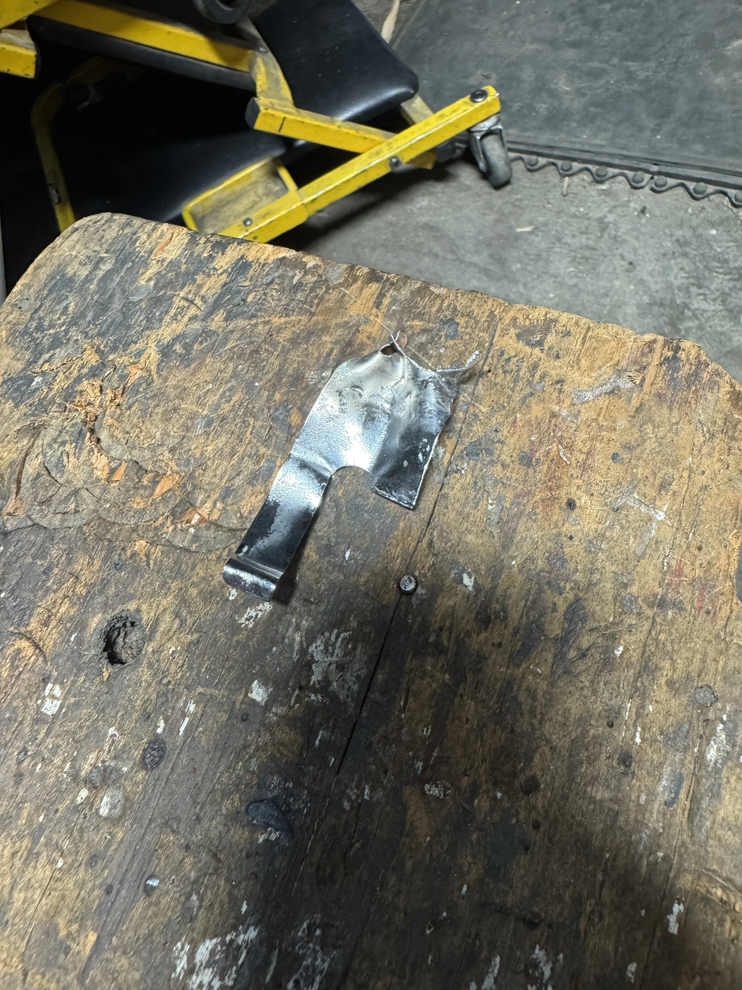
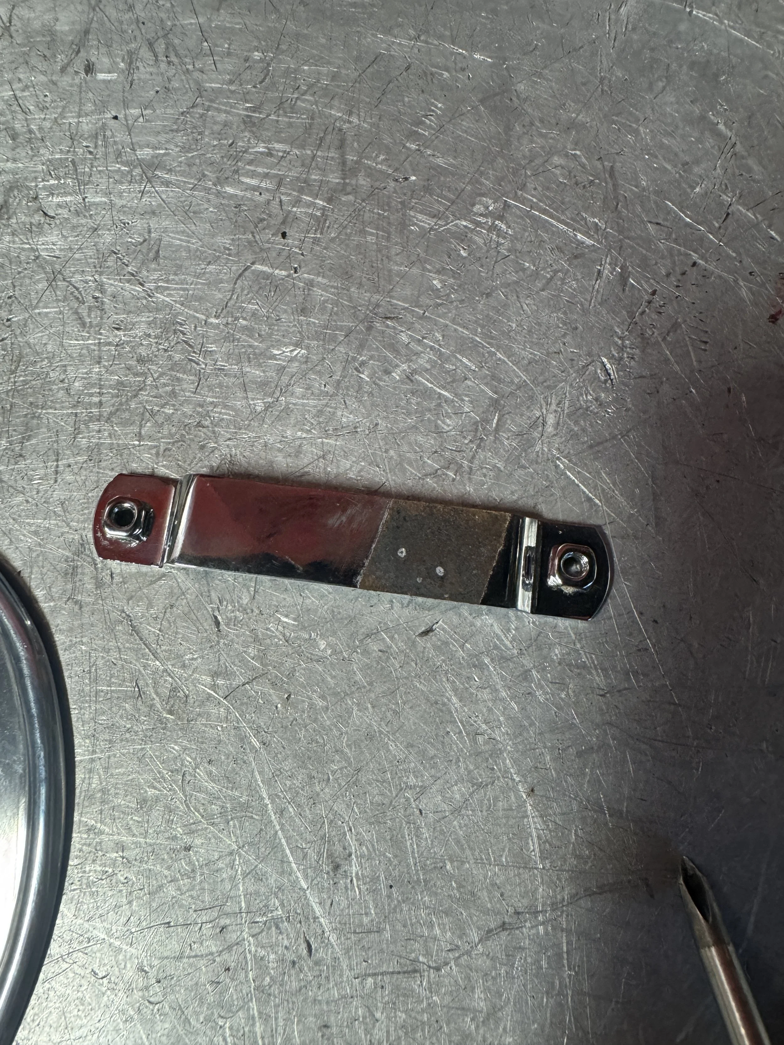
The ripped up bracket after removal.
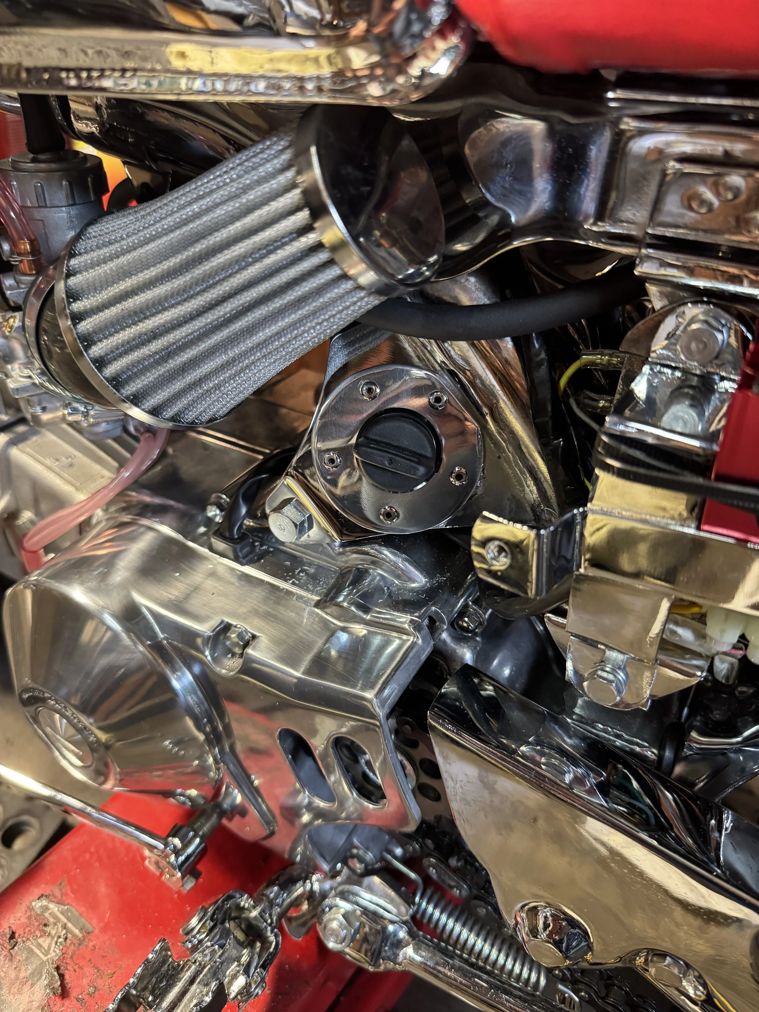
The solution that solved the problems was an aluminum mounting ring. The key switch was made to fit tightly with some wedges behind the plastic prongs that hold it in place.The key switch is now firmly held, and the ugly spot is covered up.
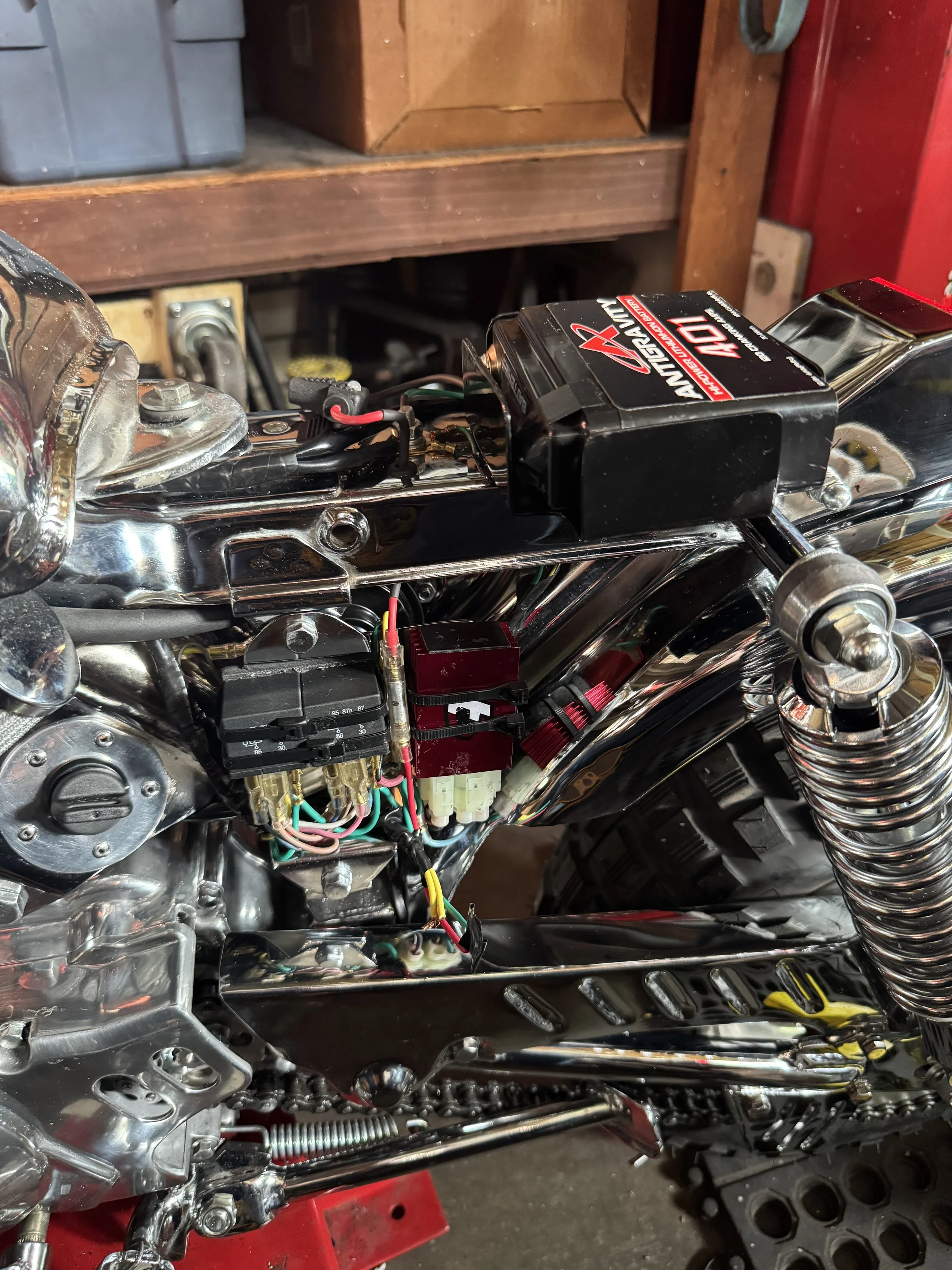
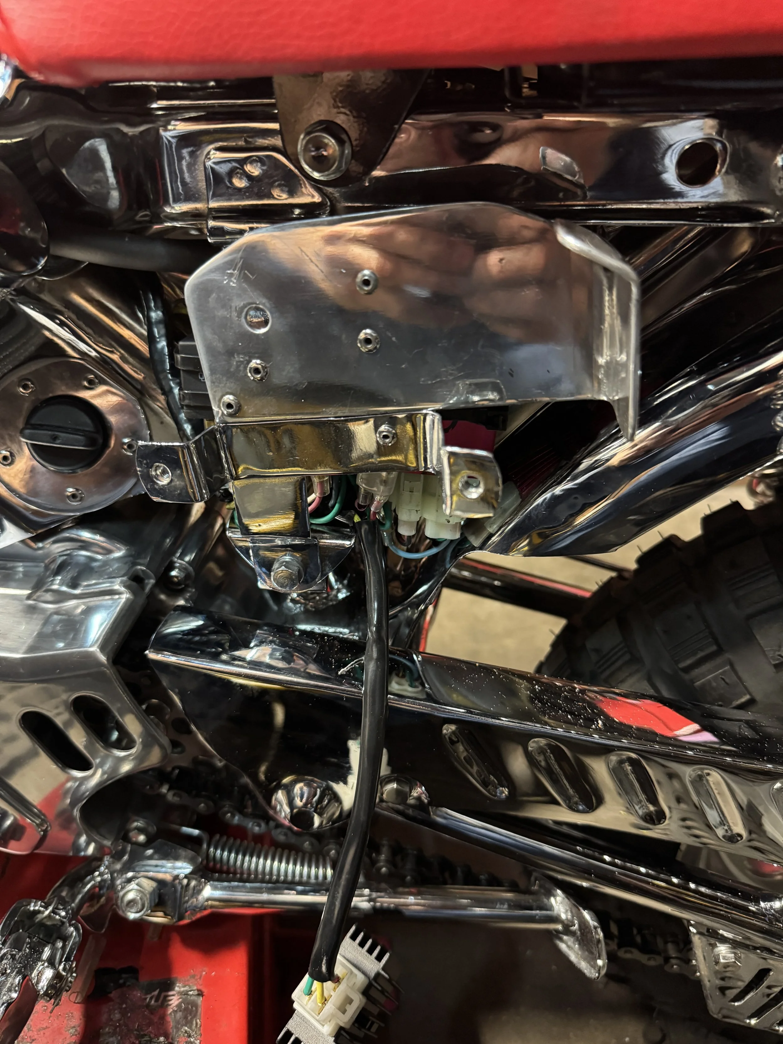
At this point, the tray is in place, and the only remaining wiring is to hook up a full-wave rectifier. The plate made to mount the CDI box and relays conceals a horn, mounted on the backside of the plate.
The mounting screws of the battery tray were counterset to keep the already tight space big enough.
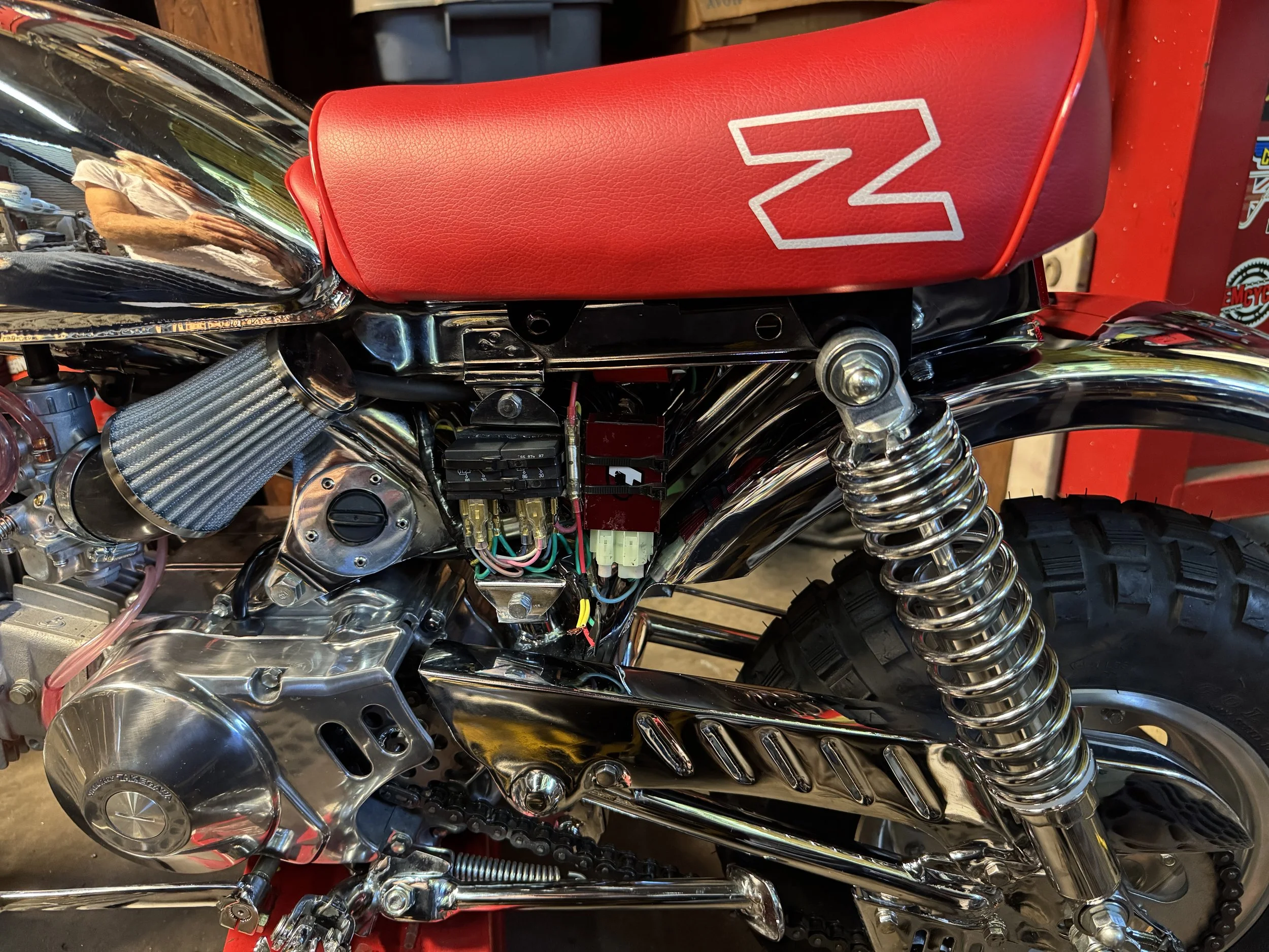
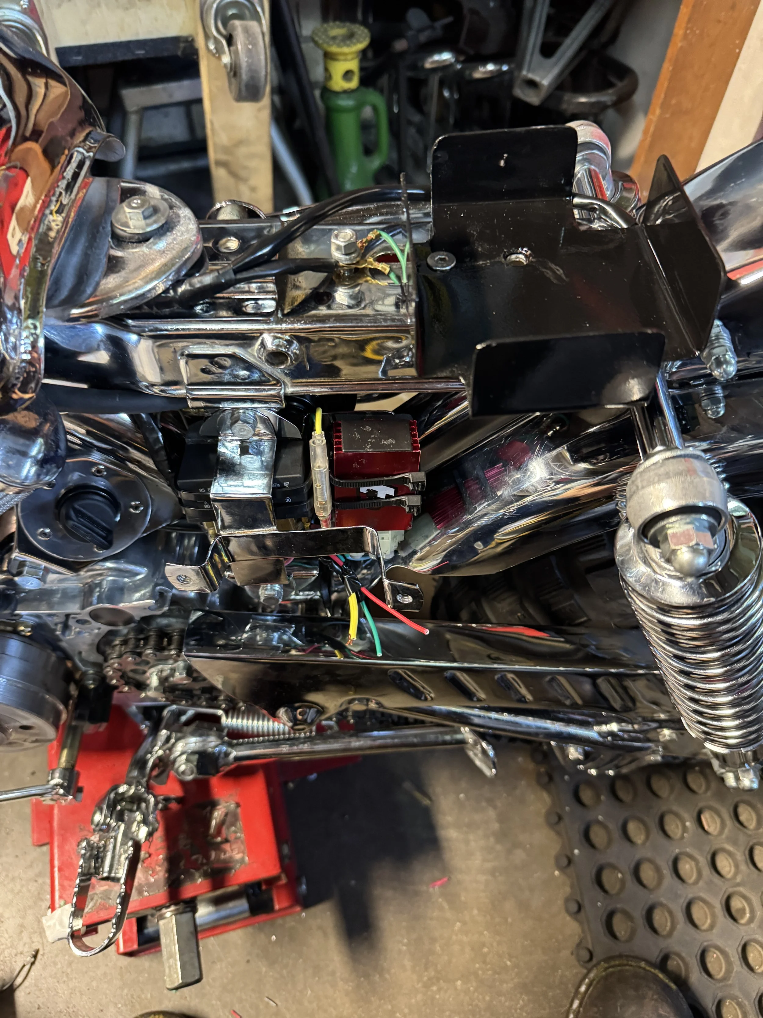
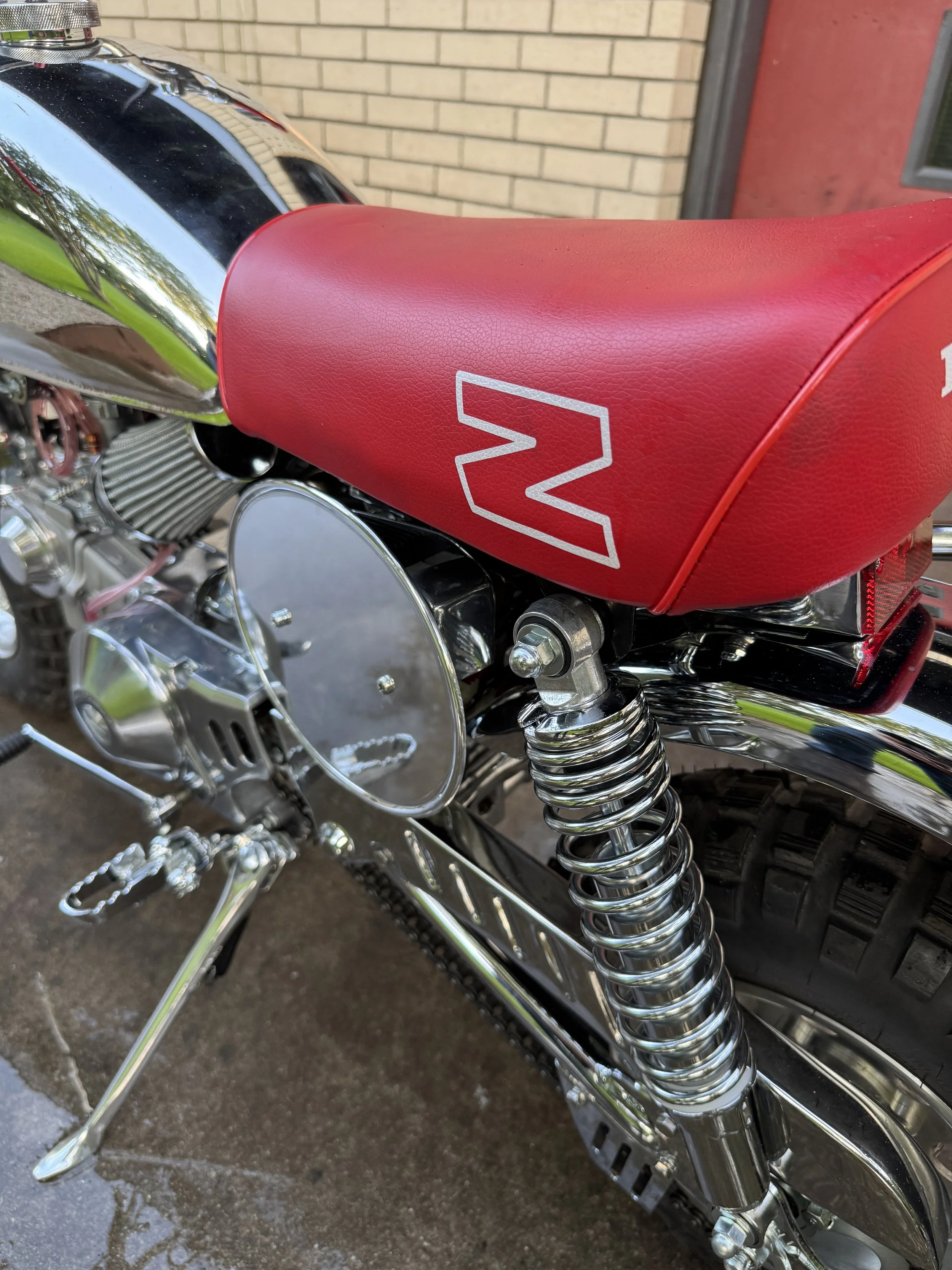
With the seat on, the battery is all but invisible. The electrical component arrangement always looks so simple when it is done, but it took a bit of time to get everything rubber mounted and arranged to fit.At this point, the relays for the lights are on the left, and the CDI box on the right. Below them, a short segment of wire is the pigtail from the stator and battery, waiting on the rectifier panel to be installed.
The mounting plate was made from .090 aluminum, and riveted onto the left number plate bracket. The part of the bracket on the right end was added to conceal the electrical parts, and keep wheel spray off them. It fit snugly to the back of the number plate.
With the plate polished, the wire harness lengthened and sheathed, the dangling rectifier is ready for mounting. The stock kick stand was not cutting it, and the chrome shop seriously altered the mounting plate, making it much thinner than original. The thinness made for a loose fit, and angling back toward the chain. The lean on the bike was also a bit much, and could use some help.
The rear view shows how the mounting bracket conceals the rectifier. A Takegawa forged aluminum kickstand was fitted to the bike. About a quarter of an inch was shaved off the bottom of the foot, to help with the lean, and a thin washer placed in the yoke to tighten up the fit.
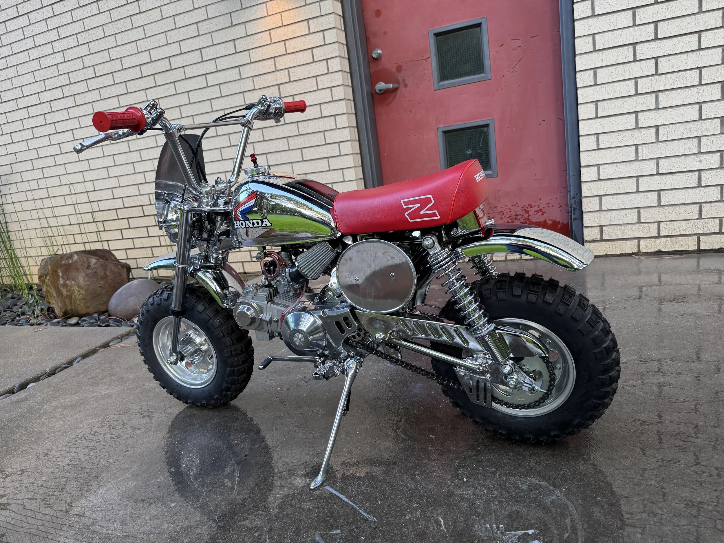
The added electrical parts are well hidden, and the Takegawa kick stand looks much better than the original. With electrical mostly done, the next thought is exploring the possibility of a speedo and tach…
While adjusting the right number plate, the tiny spot welds on the bracket gave way. This was an aftermarket bracket I had chromed. Next time, they will get some preventative re-welding. The left number plate was chopped and re-welded to match the mounting tabs on the 1979-81 frames.
Just a small change, but the number plate fits a lot better up against the muffler.