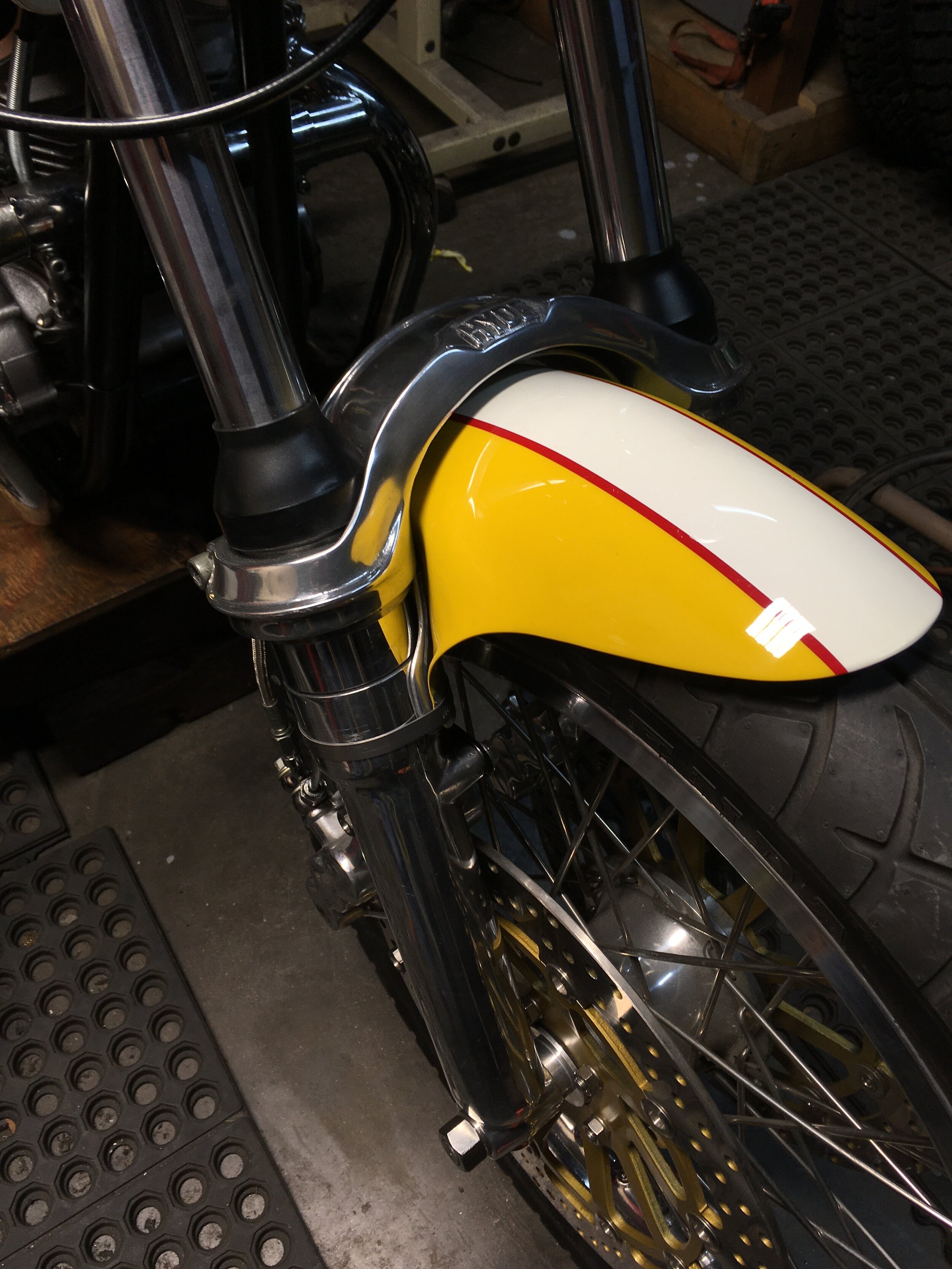
Sometimes bikes are built around here for no particular reason. This was a build that started like a lot of others…make one part and the rest just pour out after it, when you only intended to make the first part. Most everything for this build was sitting on the shelf aside from the tires and hand levers. The starting point was a 1972 Z50 tank and frame. The forks came from another ‘72, but the patina was about the same. There will be only minimal painting on this one, mostly graphics and enough paint to cover bare steel parts.

A hodge-podge of different parts. Aside from the 1972 frame and tank, there are CRF50 wheels and engine cases, 1964 CL77 rear-set footpegs, XR75 swingarm, CT70 heat shield parts, an early hardtail Z50 fork top clamp, SL70 headlight bucket, and Kawasaki KLX110 exhaust parts.

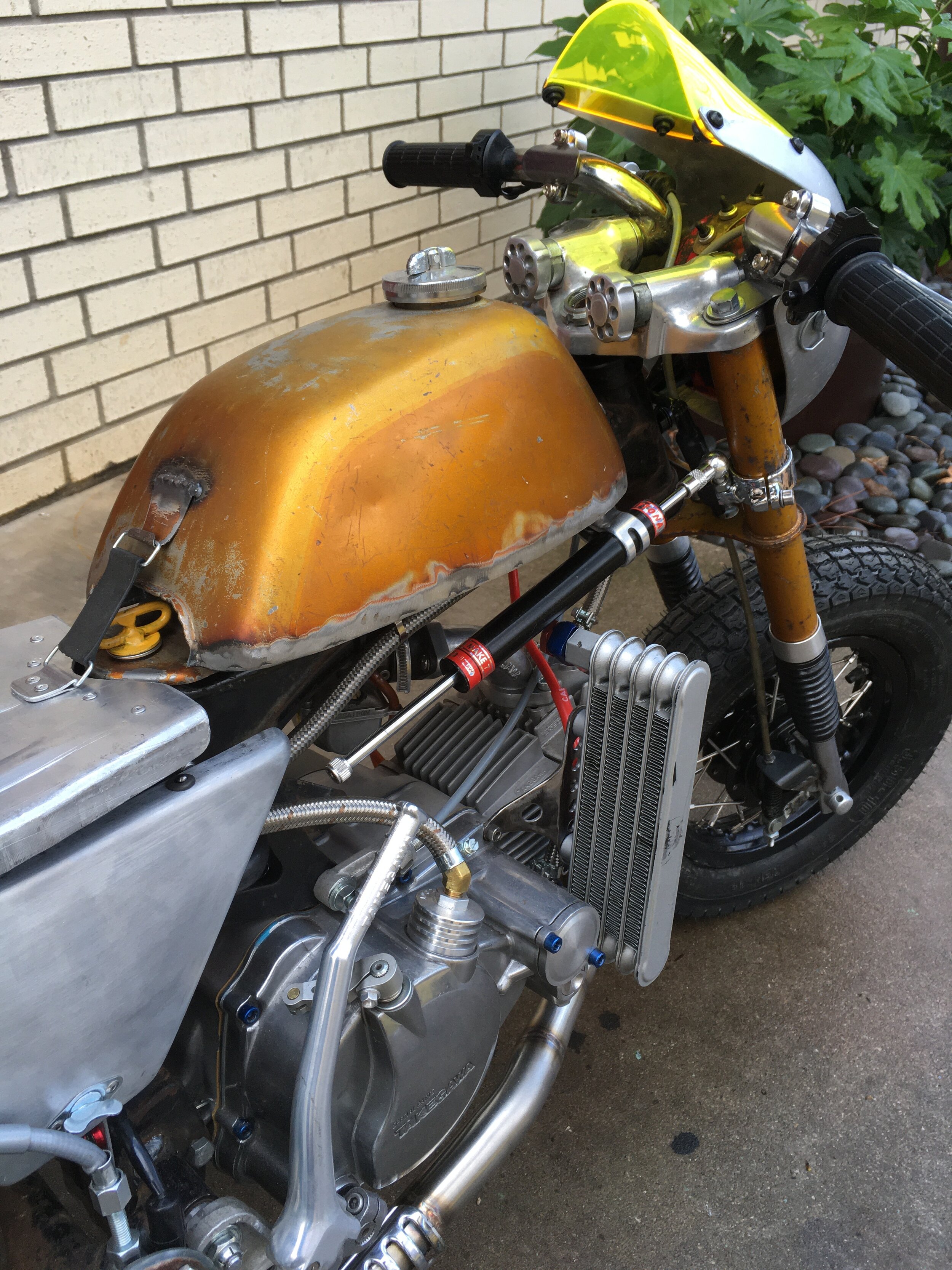
The stripes are just electrical tape mock-ups. The side covers, seat, front fairing, and chainguard are all hand formed aluminum pieces. There are a lot of Takegawa parts on the bike, The engine is a 125cc, with Takegawa crankshaft, top end, Special clutch, Super oil cooler, forged aluminum kickstarter, and Keihin PE24 kit with long intake. The muffler is a BBR D-section that has been shortened on both ends.
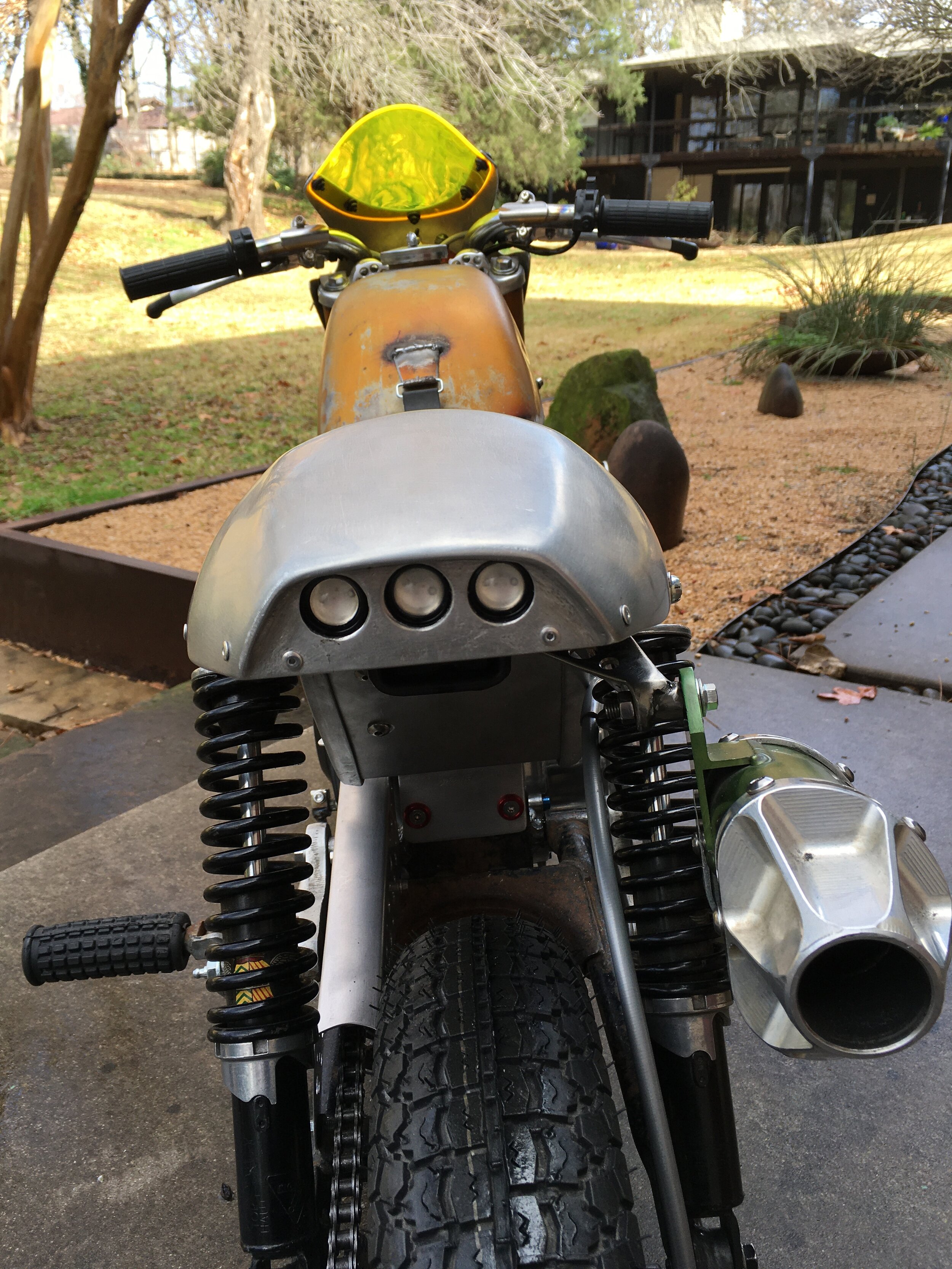
Since there is a 12 volt system with a lighting coil, I decided to go all-in on the lighting. The rear LED lights also can function as turn signals in addition to running and brake lights. There is a set of vintage KONI shocks on the rear end. The rear fairing is made from a single piece of aluminum, with no welding on any of it. Getting the recess for the light was the most difficult part.
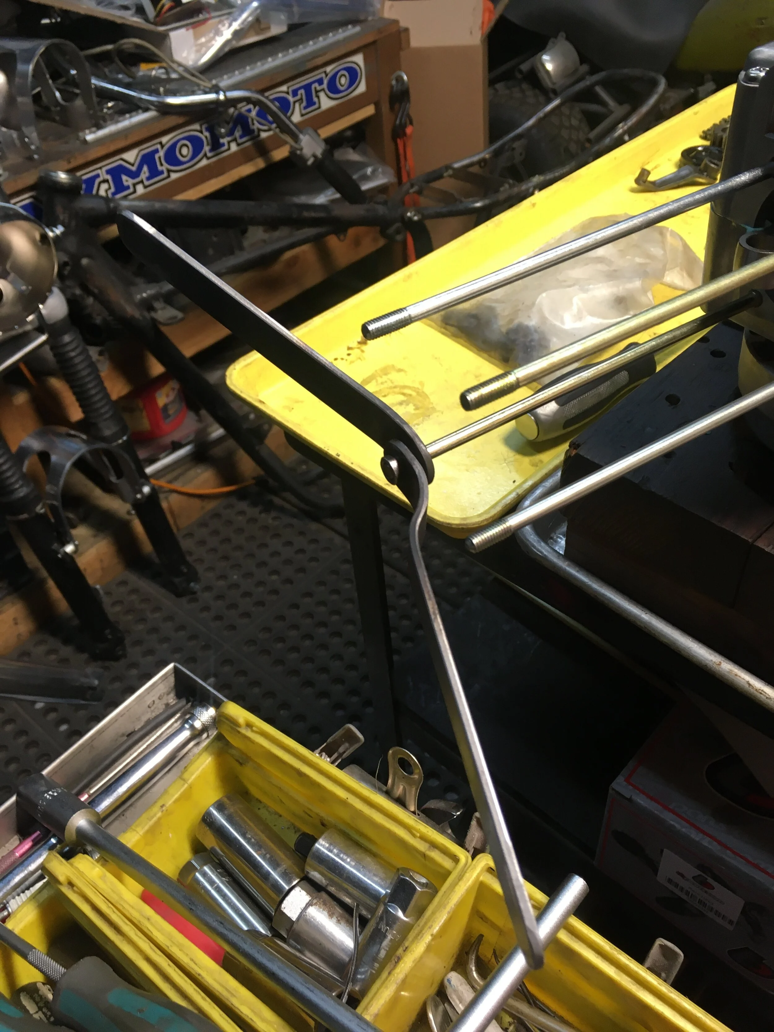
Some of the mounting system for the side covers, front fairing, and tank can be seen here. The tank, front fairing, side covers and handlebars can be stripped from the bike in seconds, without tools.

The cockpit switches are mil-spec C&K, with waterproof covers, sitting on a piece of brass. If anyone is paying attention, many of my builds have custom brass pieces, going back to the 1970’s! A special nut was cut for the steering tube cap. The handlebar knobs are custom, made from some re-pop pieces.

The Tomaselli- style hand levers are a little over-sized for the scale of the bike, but I dig how they look and function. While kind of funky, the neon yellow windscreen is growing on me. Originally intended to be plain yellow or green, the neon one was an online purchase that looked yellow in the picture.

The inner fender on the rear end helps enclose the side covers into a space housing a Kitaco carbon fiber oil vapor can, Tokyo Mods ignition, TrailTech full-wave regulator/rectifier, and a Speedcell lithium battery.


Mocking up graphics. The “MK” is for monkey killer. The 61 is the age of the builder. Not that I dig killing monkeys, just referring to the new Honda Monkey bikes. This bike was nick-named “Pony Boy” by my daughter.

Since the pictures, the graphics have been started and the chainguard was painted black. Not completely happy with the chainguard appearance in bare aluminum, maybe the black will help.