The clutch, primary drive gears, and gear selector assembly can be installed after the main engine cases are together. None of the engine case screws have been installed yet, and will be put in from the opposite side once the primary drive is done.

The kickstart return spring assembly should be put on first. The shaft should be turned fully clockwise till it stops, then the splined cog is slid partially down the shaft with the tip of the cog contacting the engine case as in the above picture. Using a screwdriver or a hook, the return spring is pulled so the end loops around the engine case boss. Once the spring is there, the cog can be pushed down fully till the groove for the C-clip can be seen on the kick shaft.

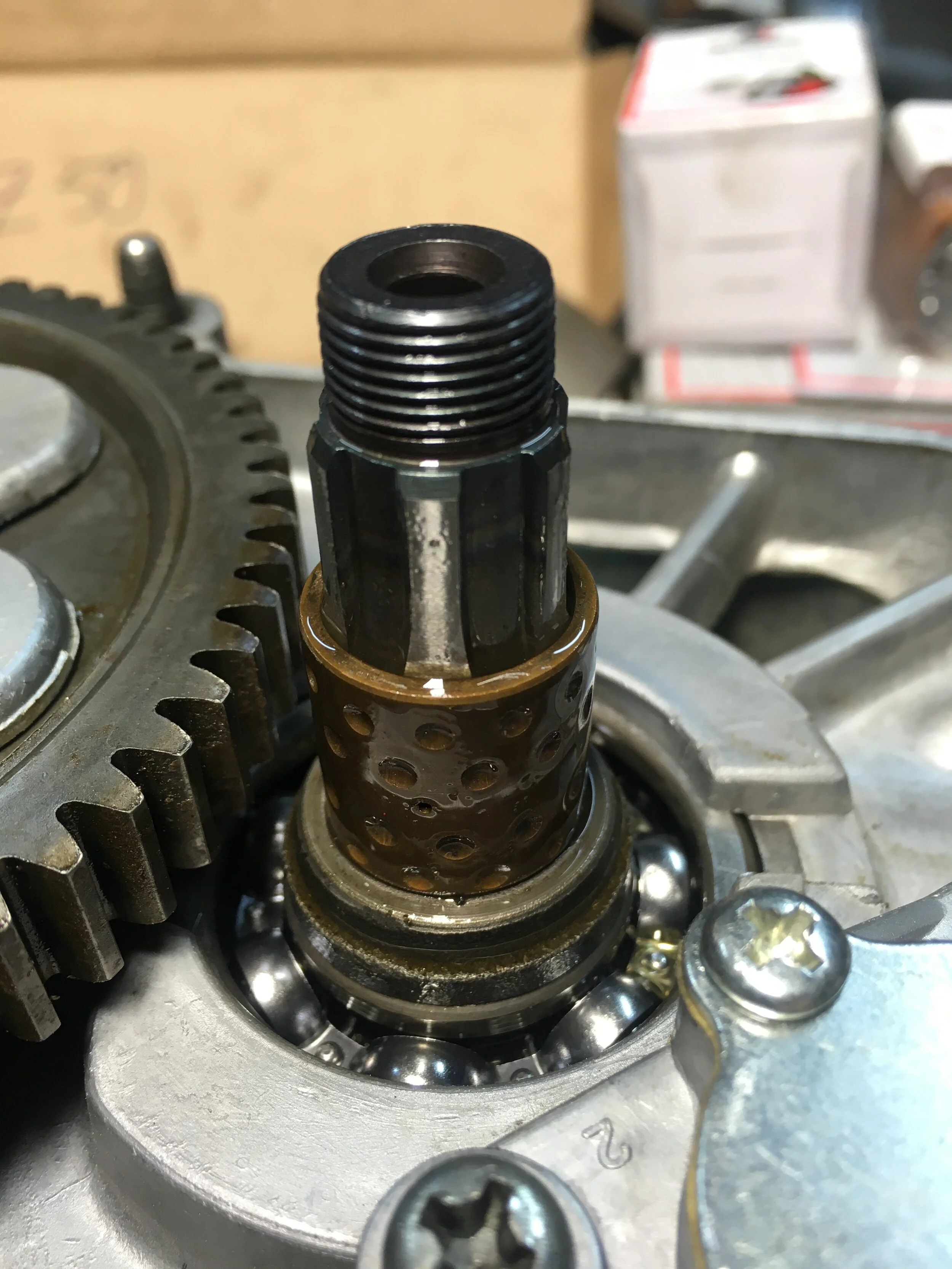
The high volume oil pump used for this build has a collar that must be fitted in the drive shaft hole to support the drive shaft. Don’t forget to use a new gasket.

The oil pump is installed being careful to make sure the shaft and pump mesh. The drive sprocket can be turned to get them to mesh correctly. The three larger screws are the ones securing the pump. The gear selector assembly goes on next, with the shaft dropping in the hole, the end of the arm contacting the gear selector star pins, being sure the spring that goes on the shaft is contacting the engine stud correctly. The extended ends of the spring should be on opposite sides of the shaft. The shift star can be put on now, or before placing the selector arm in the case. Lastly, the small arm with the roller on it (the shift detent arm) can be put on, making sure it moves freely once its securing bolt has been tightened. Notice that the C-clip for the kick shaft assembly is in place, and the return spring around the engine case boss.
If your crank is new, you will need to put the spacer and bronze bushing on before the clutch and drive gear are put on. Use plenty of oil assembling these parts.

The clutch drive gear drops in place, and the larger primary gear slips over the shaft, secured by a C-clip. The oil filter screen can be put in place.

The clutch drops onto its shaft, making sure the gear beneath it meshes with the backside of the clutch, the large primary gear, and the clutch/crankshaft splines. It will be necessary to turn the clutch and large gear while wiggling the clutch to get it all to mesh correctly. The clutch nut is put on after the locking tab and special domed washer.

This picture was from the disassembly, but using it to show the clutch cover in place.

This is the auto clutch actuator assembly in place. Usually I will wait to put these parts on till after the opposite side of the engine is done. The reason is that once these parts are on, the outer engine side cover has to be put on to keep them in place. Having the cover in place makes it harder to work on the stator side of the engine because of the roundness of the cover. This engine stand secures the engine even with the cover in place, but will contact the cover, marring a newly painted cover. The actuator assembly just floats until the cover is on, and centering it so the cover contacts it correctly is much more difficult if the engine is upright.

This is the clutch adjuster screw assembly. It fits on the inside of the cover with the screw passing through the center hole, and the post in the blind hole. On the opposite side, an O-ring, washer and nut will be placed to secure and seal it.