Finishing stages for the 1974 Norton Commando Cafe.

The

Another killer paint job by Jason Small of Dallas, Texas. Jason’s attention to detail and knowledge of correct original paint schemes is second to none.
Another killer paint job by Jason Small of Dallas, Texas. Jason’s attention to detail and knowledge of correct original paint schemes is second to none.

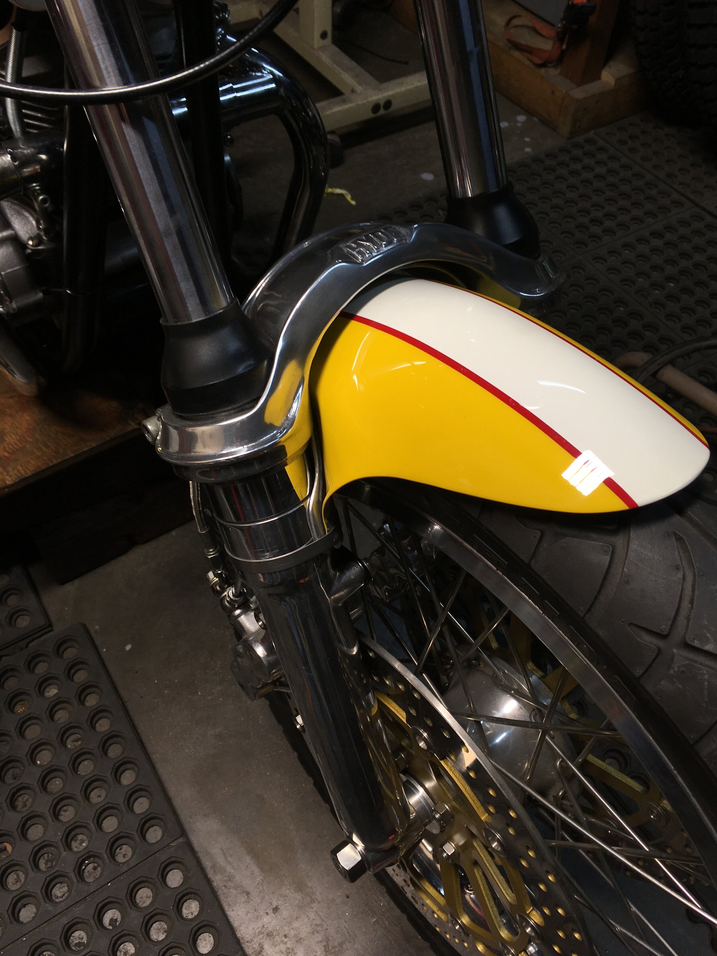
Quite happy with how the front fender fits with the Norman Hyde fork brace. The front wheel and brake assembly are from Don Pender.

Quite happy with how the front fender fits with the Norman Hyde fork brace. The front wheel and brake assembly are from Don Pender.

The color scheme and pallet was chosen by the owner. The lighting makes it look lighter and brighter in this picture. The actual color is a strong, deep yellow and red.

The color scheme and pallet was chosen by the owner. The lighting makes it look lighter and brighter in this picture. The actual color is a strong, deep yellow and red.

Still need some final fitting and the seat, but getting there!

Still need some final fitting and the seat, but getting there!

IMG_1984.JPG
Because of my limited aluminum welding skills, all the parts are made from a single piece. In the case of the front fairing, the edges are rolled over a steel rod sub-structure, making it very light.

Because of my limited aluminum welding skills, all the parts are made from a single piece. In the case of the front fairing, the edges are rolled over a steel rod sub-structure, making it very light.

New bezels and glass were put on the clocks. In order to roll the bezel edges, a jewelers burnisher and a C-clamp were used to get it flattened out nicely..

New bezels and glass were put on the clocks. In order to roll the bezel edges, a jewelers burnisher and a C-clamp were used to get it flattened out nicely..

The tach dial looks better with the hand re-painted fluorescent orange.

The tach dial looks better with the hand re-painted fluorescent orange.

I have only sent aluminum out for polishing twice, but probably never again. This time, not only did there do a sub-par job, they completely obliterated the timing marks on the primary cover. This one is a replacement.

I have only sent aluminum out for polishing twice, but probably never again. This time, not only did there do a sub-par job, they completely obliterated the timing marks on the primary cover. This one is a replacement.

There is an inner brace that runs on the outside of the front fender. Because the mounting point is on the lower ears of the fender, there would be a lot of potential for vibration and flexing, and the inevitable stress cracking that follow. The bra…

There is an inner brace that runs on the outside of the front fender. Because the mounting point is on the lower ears of the fender, there would be a lot of potential for vibration and flexing, and the inevitable stress cracking that follow. The brace hugs the sides of the fender all the way to the crown of the fender, with rubber to soften vibrations. The result is a rigid fender mount that should resist cracking.

Z50 Engine building part three. The top end.

Once the primary drive is assembled on the other side of the engine, it is flipped over and the case screws put in. A single bolt holds the chain tensioner arm in place. It should move freely when tightened. The mainshaft and shift shaft seals can b…

Once the primary drive is assembled on the other side of the engine, it is flipped over and the case screws put in. A single bolt holds the chain tensioner arm in place. It should move freely when tightened. The mainshaft and shift shaft seals can be pressed in place with a socket and a hammer.

The special washer and bolt that hold the transmission shift drum in place are installed.

The special washer and bolt that hold the transmission shift drum in place are installed.

The timing chain tensioner roller is simply dropped in place. It is held in place by the stator plate. The plunger and spring are placed in the bore till they contact the chain tensioner arm. There  is a flat side on this particular tensioner plunge…

The timing chain tensioner roller is simply dropped in place. It is held in place by the stator plate. The plunger and spring are placed in the bore till they contact the chain tensioner arm. There is a flat side on this particular tensioner plunger, where the locking screw contacts with it. The hole down and to the left of the shifter shaft is where the locking bolt and nut go.

Two of the three chain tensioner plunger styles. The lower one is the earlier one, and the upper one came after, followed by another steel plunger with holes perforating it.

Two of the three chain tensioner plunger styles. The lower one is the earlier one, and the upper one came after, followed by another steel plunger with holes perforating it.

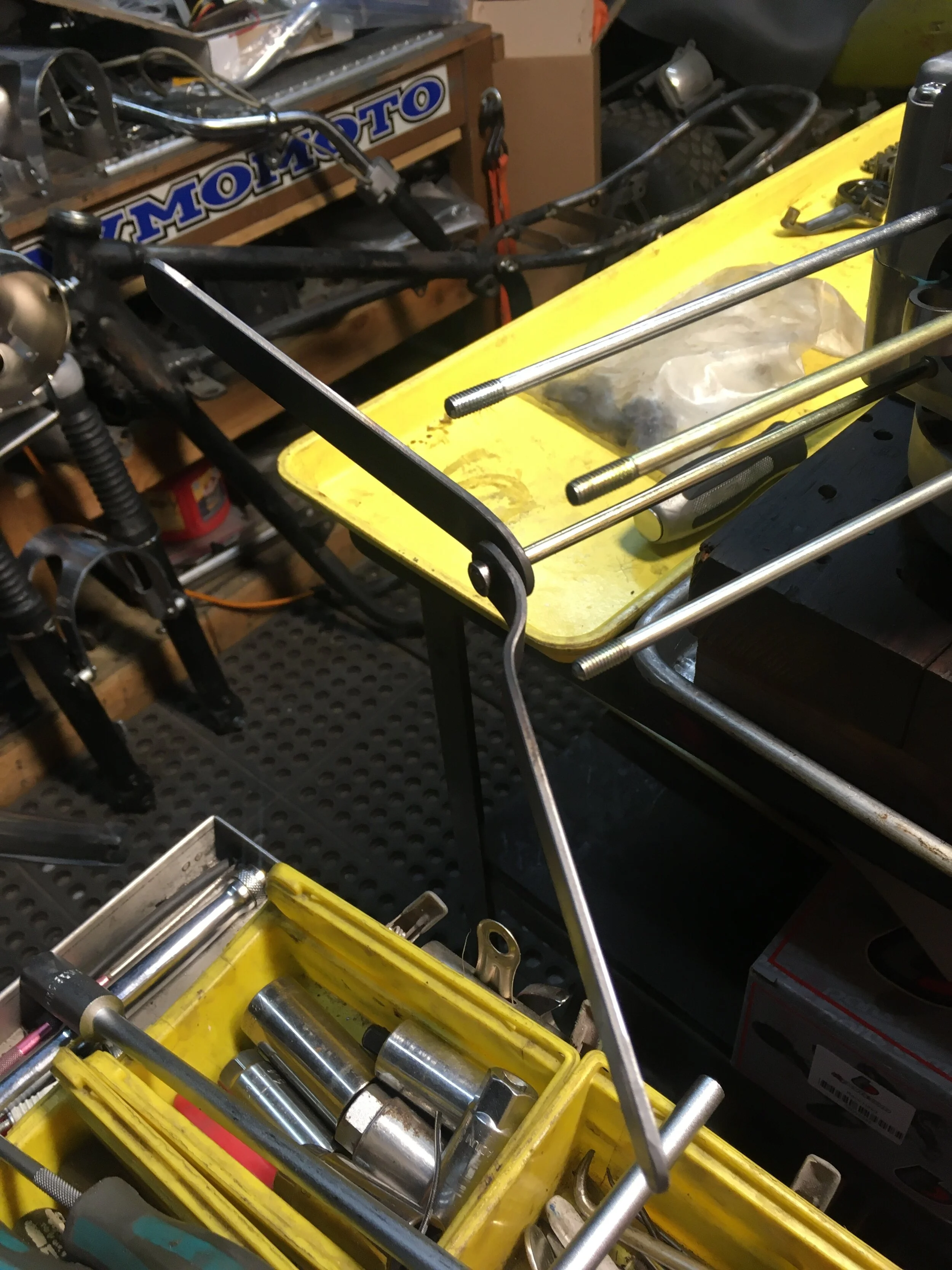
There are two lengths of engine head studs. The longer ones go on the left side of the engine, with the engine dowels at their base. The studs can be snugged up using two nuts tightened against one another. These are some homemade levers with the bo…

There are two lengths of engine head studs. The longer ones go on the left side of the engine, with the engine dowels at their base. The studs can be snugged up using two nuts tightened against one another. These are some homemade levers with the bolts welded on to avoid having to use a pair of wrenches.

With the studs and locator dowels in place, the paper cylinder base gasket goes on along with the flat o-ring that fits in the round opening on the right of the picture.

With the studs and locator dowels in place, the paper cylinder base gasket goes on along with the flat o-ring that fits in the round opening on the right of the picture.

The piston rings need to be put on. The shiny one on the right goes at the top of the piston, the dark one in the middle, and the three-piece oil ring goes on the bottom. They are put on starting with the wavy oil ring followed by the skinny rings t…

The piston rings need to be put on. The shiny one on the right goes at the top of the piston, the dark one in the middle, and the three-piece oil ring goes on the bottom. They are put on starting with the wavy oil ring followed by the skinny rings that go on each side of it. The middle ring goes on next, and the top shiny ring last. The gaps at the end of the rings should be staggered so they do not all lie in the same location.

Once the rings are on, the piston can be joined to the crankshaft. It is easier to place the wrist pin clip into one side of the piston before putting the wrist pin in. Be sure to place the piston with the intake side toward the top of the engine. T…

Once the rings are on, the piston can be joined to the crankshaft. It is easier to place the wrist pin clip into one side of the piston before putting the wrist pin in. Be sure to place the piston with the intake side toward the top of the engine. There is usually a stamp with “IN” marked on the intake side, or an arrow is sometimes used to point it out. If neither of those marks are there, the side with the larger valve recess is the intake side.

There is a small flat o-ring that goes around the lower right engine stud and fits into the head gasket. There is a second larger flat o-ring that goes in the larger opening seen at the upper right of the picture.

There is a small flat o-ring that goes around the lower right engine stud and fits into the head gasket. There is a second larger flat o-ring that goes in the larger opening seen at the upper right of the picture.

To set the valve timing, the flywheel needs to be placed on the shaft and the crank rotated until the “T” mark lines up with the notch at the top of the engine case.

To set the valve timing, the flywheel needs to be placed on the shaft and the crank rotated until the “T” mark lines up with the notch at the top of the engine case.

Using a screwdriver or round rod, the timing chain is pulled tight, keeping it between the studs. The place where it comes to a peak is the pin that will be lined up with the mark on the cam sprocket. The cam sprocket is placed on the chain and fed …

Using a screwdriver or round rod, the timing chain is pulled tight, keeping it between the studs. The place where it comes to a peak is the pin that will be lined up with the mark on the cam sprocket. The cam sprocket is placed on the chain and fed through the head to line up with the cam. The cam should be in the top dead center position. You can tell it is in the right position if the cam turns freely about a quarter turn or more. If it is in the wrong position, the valves will be engaged, and the cam will be difficult to turn.

The small mark on the cam sprocket should line up with the mark on the head, making sure the “T” mark on the flywheel is still aligned.

The small mark on the cam sprocket should line up with the mark on the head, making sure the “T” mark on the flywheel is still aligned.

Z50 engine building part two. Assembling the primary drive.

The clutch, primary drive gears, and gear selector assembly can be installed after the main engine cases are together. None of the engine case screws have been installed yet, and will be put in from the opposite side once the primary drive is done.

The kickstart return spring assembly should be put on first. The shaft should be turned fully clockwise till it stops, then the splined cog is slid partially down the shaft with the tip of the cog contacting the engine case as in the above picture. …

The kickstart return spring assembly should be put on first. The shaft should be turned fully clockwise till it stops, then the splined cog is slid partially down the shaft with the tip of the cog contacting the engine case as in the above picture. Using a screwdriver or a hook, the return spring is pulled so the end loops around the engine case boss. Once the spring is there, the cog can be pushed down fully till the groove for the C-clip can be seen on the kick shaft.

The high volume oil pump used for this build has a collar that must be fitted in the drive shaft hole to support the drive shaft. Don’t forget to use a new gasket.

The high volume oil pump used for this build has a collar that must be fitted in the drive shaft hole to support the drive shaft. Don’t forget to use a new gasket.

The oil pump is installed being careful to make sure the shaft and pump mesh. The drive sprocket can be turned to get them to mesh correctly. The three larger screws are the ones securing the pump. The gear selector assembly goes on next, with the s…

The oil pump is installed being careful to make sure the shaft and pump mesh. The drive sprocket can be turned to get them to mesh correctly. The three larger screws are the ones securing the pump. The gear selector assembly goes on next, with the shaft dropping in the hole, the end of the arm contacting the gear selector star pins, being sure the spring that goes on the shaft is contacting the engine stud correctly. The extended ends of the spring should be on opposite sides of the shaft. The shift star can be put on now, or before placing the selector arm in the case. Lastly, the small arm with the roller on it (the shift detent arm) can be put on, making sure it moves freely once its securing bolt has been tightened. Notice that the C-clip for the kick shaft assembly is in place, and the return spring around the engine case boss.

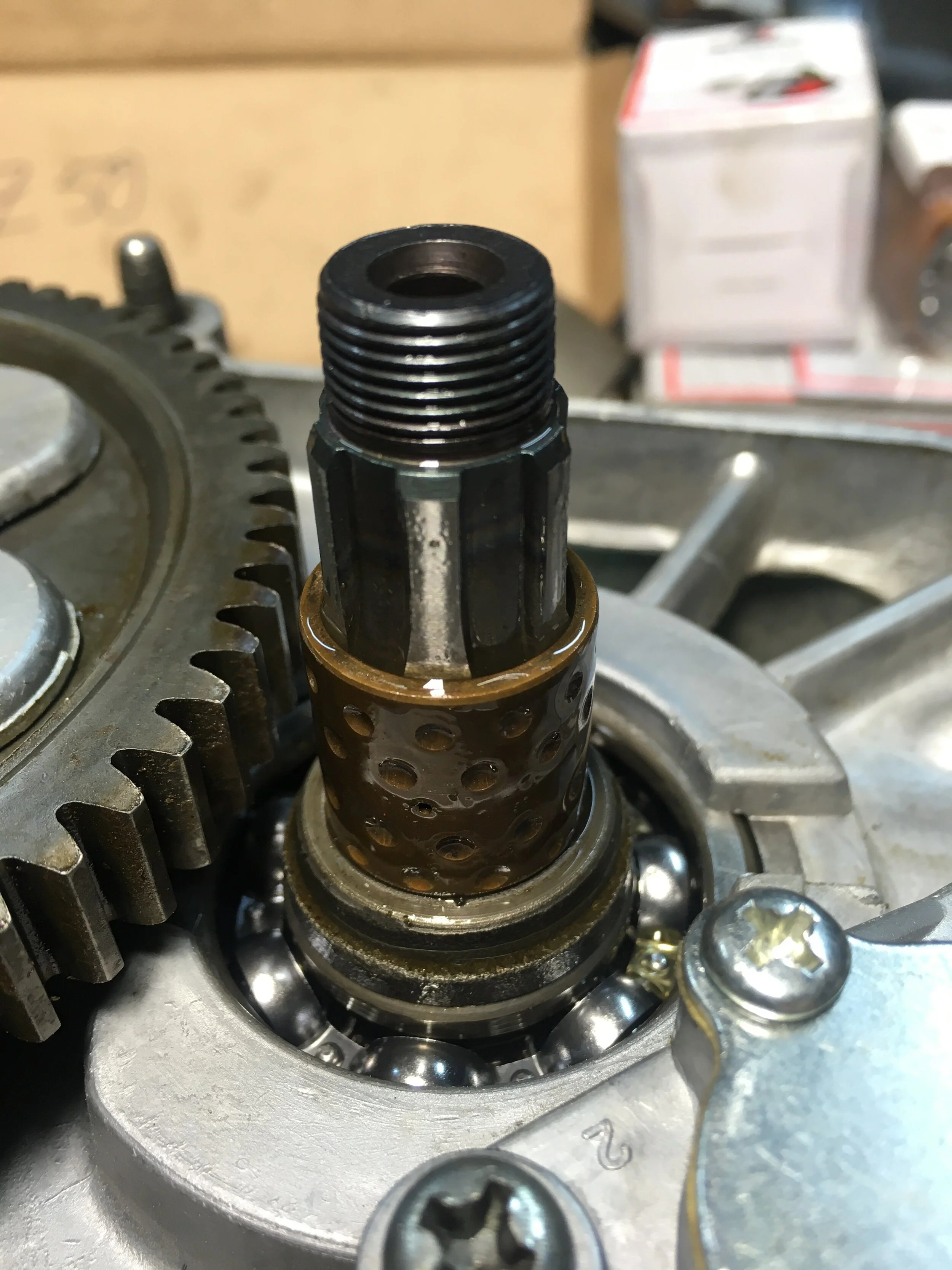
If your crank is new, you will need to put the spacer and bronze bushing on before the clutch and drive gear are put on. Use plenty of oil assembling these parts.

If your crank is new, you will need to put the spacer and bronze bushing on before the clutch and drive gear are put on. Use plenty of oil assembling these parts.

The clutch drive gear drops in place, and the larger primary gear slips over the shaft, secured by a C-clip. The oil filter screen can be put in place.

The clutch drive gear drops in place, and the larger primary gear slips over the shaft, secured by a C-clip. The oil filter screen can be put in place.

The clutch drops onto its shaft, making sure the gear beneath it meshes with the backside of the clutch, the large primary gear, and the clutch/crankshaft splines. It will be necessary to turn the clutch and large gear while wiggling the clutch to g…

The clutch drops onto its shaft, making sure the gear beneath it meshes with the backside of the clutch, the large primary gear, and the clutch/crankshaft splines. It will be necessary to turn the clutch and large gear while wiggling the clutch to get it all to mesh correctly. The clutch nut is put on after the locking tab and special domed washer.

This picture was from the disassembly, but using it to show the clutch cover in place.

This picture was from the disassembly, but using it to show the clutch cover in place.

This is the auto clutch actuator assembly in place. Usually I will wait to put these parts on till after the opposite side of the engine is done. The reason is that once these parts are on, the outer engine side cover has to be put on to keep them i…

This is the auto clutch actuator assembly in place. Usually I will wait to put these parts on till after the opposite side of the engine is done. The reason is that once these parts are on, the outer engine side cover has to be put on to keep them in place. Having the cover in place makes it harder to work on the stator side of the engine because of the roundness of the cover. This engine stand secures the engine even with the cover in place, but will contact the cover, marring a newly painted cover. The actuator assembly just floats until the cover is on, and centering it so the cover contacts it correctly is much more difficult if the engine is upright.

This is the clutch adjuster screw assembly. It fits on the inside of the cover with the screw passing through the center hole, and the post in the blind hole. On the opposite side, an O-ring, washer and nut will be placed to secure and seal it.

This is the clutch adjuster screw assembly. It fits on the inside of the cover with the screw passing through the center hole, and the post in the blind hole. On the opposite side, an O-ring, washer and nut will be placed to secure and seal it.