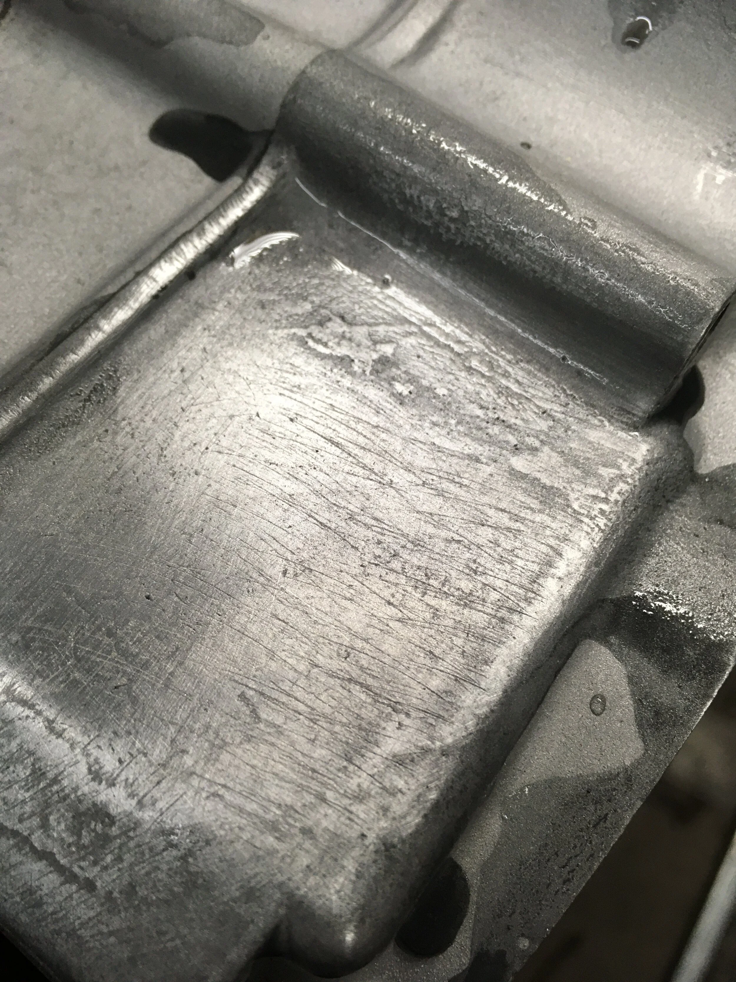
Once the primary drive is assembled on the other side of the engine, it is flipped over and the case screws put in. A single bolt holds the chain tensioner arm in place. It should move freely when tightened. The mainshaft and shift shaft seals can be pressed in place with a socket and a hammer.

The special washer and bolt that hold the transmission shift drum in place are installed.

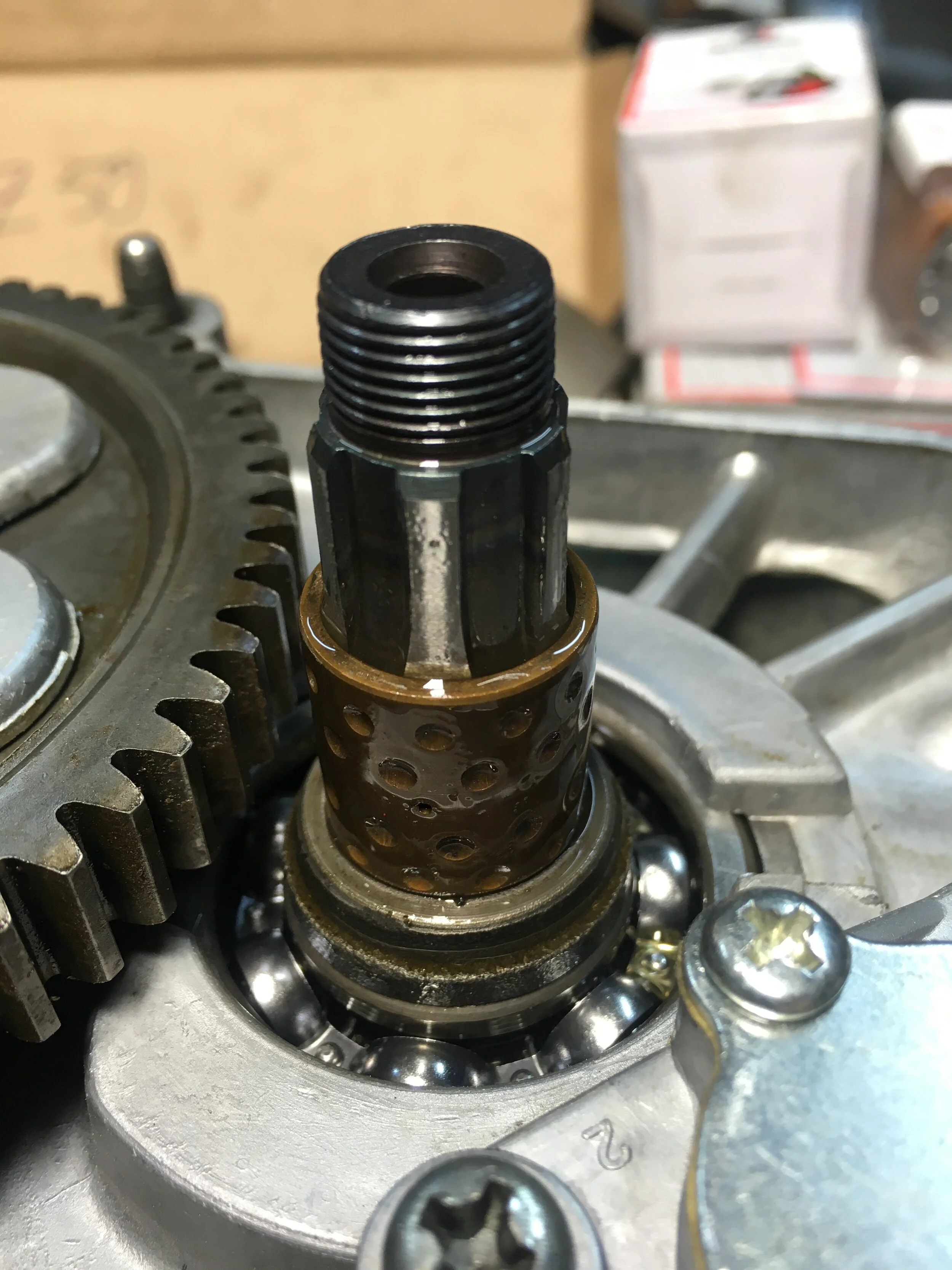
The timing chain tensioner roller is simply dropped in place. It is held in place by the stator plate. The plunger and spring are placed in the bore till they contact the chain tensioner arm. There is a flat side on this particular tensioner plunger, where the locking screw contacts with it. The hole down and to the left of the shifter shaft is where the locking bolt and nut go.

Two of the three chain tensioner plunger styles. The lower one is the earlier one, and the upper one came after, followed by another steel plunger with holes perforating it.
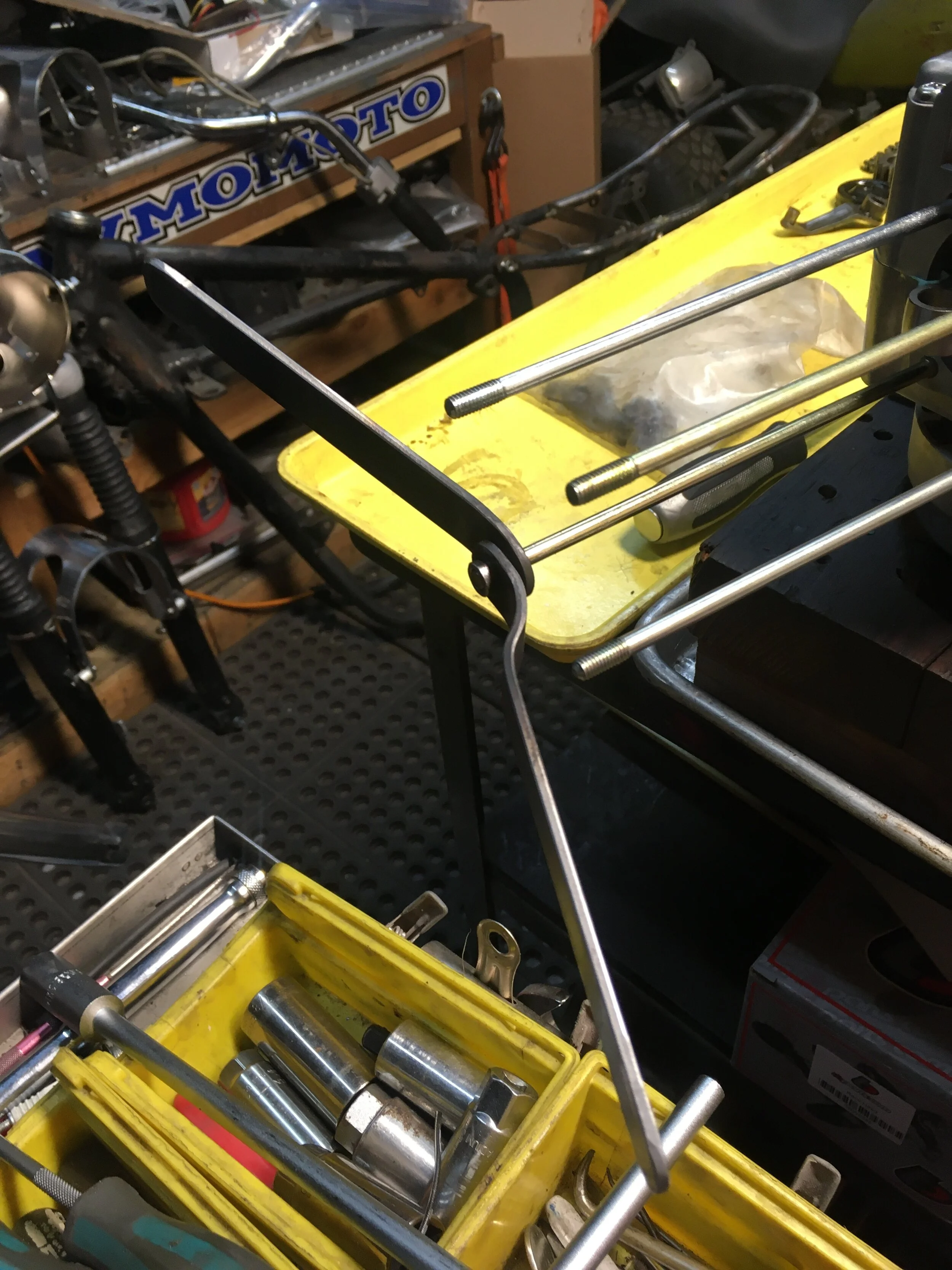
There are two lengths of engine head studs. The longer ones go on the left side of the engine, with the engine dowels at their base. The studs can be snugged up using two nuts tightened against one another. These are some homemade levers with the bolts welded on to avoid having to use a pair of wrenches.

With the studs and locator dowels in place, the paper cylinder base gasket goes on along with the flat o-ring that fits in the round opening on the right of the picture.

The piston rings need to be put on. The shiny one on the right goes at the top of the piston, the dark one in the middle, and the three-piece oil ring goes on the bottom. They are put on starting with the wavy oil ring followed by the skinny rings that go on each side of it. The middle ring goes on next, and the top shiny ring last. The gaps at the end of the rings should be staggered so they do not all lie in the same location.

Once the rings are on, the piston can be joined to the crankshaft. It is easier to place the wrist pin clip into one side of the piston before putting the wrist pin in. Be sure to place the piston with the intake side toward the top of the engine. There is usually a stamp with “IN” marked on the intake side, or an arrow is sometimes used to point it out. If neither of those marks are there, the side with the larger valve recess is the intake side.

There is a small flat o-ring that goes around the lower right engine stud and fits into the head gasket. There is a second larger flat o-ring that goes in the larger opening seen at the upper right of the picture.

To set the valve timing, the flywheel needs to be placed on the shaft and the crank rotated until the “T” mark lines up with the notch at the top of the engine case.

Using a screwdriver or round rod, the timing chain is pulled tight, keeping it between the studs. The place where it comes to a peak is the pin that will be lined up with the mark on the cam sprocket. The cam sprocket is placed on the chain and fed through the head to line up with the cam. The cam should be in the top dead center position. You can tell it is in the right position if the cam turns freely about a quarter turn or more. If it is in the wrong position, the valves will be engaged, and the cam will be difficult to turn.

The small mark on the cam sprocket should line up with the mark on the head, making sure the “T” mark on the flywheel is still aligned.